
Low Voltage Driver Guide
About
All Luke Lamp Co. fixtures require remotely-mounted drivers (also known as transformers, inverters, or ballasts), which convert line voltage to low voltage. These drivers are not integrated or built into the fixture and must be mounted remotely.
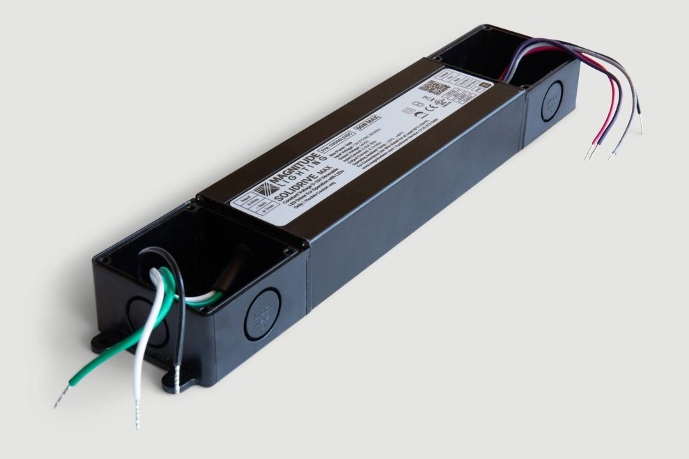
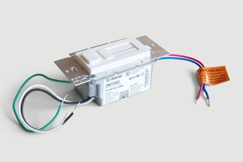
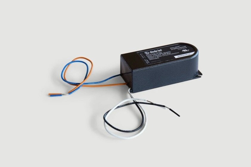
Luke Lamp Co. offers a selection of three drivers, which are generally included free of charge with our fixtures: the Universal Remote Driver, SWITCHEX Combined Driver/Dimmer Switch, and the MikroDIM Driver. To learn more about each driver and determine the appropriate one for your installation, please refer to our Driver Specification Guide.
FAQ
-
Yes! Once you select the right driver for your order, we will include it at no additional charge.
-
The maximum distance that the driver can be mounted away from the fixture depends on the fixture wattage and the wire gauge used. Please refer to the Voltage Drop Chart for more information on this.
-
There are several factors that will impact this answer, including the type of driver you wish to use, the wattages of the fixtures you’re ordering, and the fixture locations in your space in relation to one another. In some cases you may be able to utilize a single driver with multiple fixtures. For example, if you order two 20W sconces and plan to use the Universal Remote Driver, it's likely that both can share a single driver assuming they will be located in the same vicinity (for example, on either side of a bed or mirror). Your Account Manager will advise you on your options during the ordering process.
-
You are free to source drivers separately if preferred. It must be a constant voltage, 24VDC driver at the appropriate wattage. We are happy to talk directly to your electrician if they have any questions.
-
The Universal Remote Driver is universal voltage (meaning it works with line voltage from 120V-277VAC) so it should be compatible throughout the world. The SWITCHEX and MikroDIM drivers are only compatible with 120VAC input/mains voltage.
For clients in the EU, in order to comply with CE certification requirements, we cannot supply the drivers. However, your electrician should be able to source compatible constant voltage 24VDC drivers locally. They can reach out to us directly if they have any questions on this!
-
Yes, we do ask that you select the driver in order for us to begin production to avoid any delays. However, we are more than happy to swap out your driver for another option if you determine that the one you selected won’t work. Keep in mind that for some fixtures, only the Universal Remote Driver is compatible. Your Account Manager will discuss your options during the ordering process.
-
Please refer to our Driver Specification Guide. If still unsure, please provide the specs of the system you're using and we can confirm compatibility with the driver manufacturer.
-
Please contact us right away and we can discuss your options! We might have an alternative option that will work in your space. You can reach us at 914-294-2024 (press 2 for Technical Assistance). Please have your Invoice Number available so we can look up your order.
-
There can be several different reasons for this depending on the driver and dimmer/control system that you are using. Our Technical Team can walk your electrician through some troubleshooting steps. In the unlikely event that a new driver is needed, we will expedite shipment to ensure it reaches you as quickly as possible - we understand that time is of the essence!
-
If your fixture is connected directly to line voltage (without using the driver), it will immediately damage the internal LED modules and will no longer be operable. Some ways you can tell that this happened is if: (1) The light appears very dim, (2) the LEDs are flickering, (3) some sections appear lit while others are dim or dark, (4) the light isn’t turning on at all. When this happens the LEDs need to be replaced by us. Please contact us at 914-294-2024 (or contact your Account Manager directly) to discuss the next steps in the replacement process. We will resolve this as quickly and painlessly as possible!
Voltage Drop Chart

Please utilize this chart to determine the appropriate wire gauge to use based on the wattage of your fixture(s) and the distance between the driver(s) and fixture(s). This is an important step in ensuring that there is no impact to the output of the light (no dimming, flickering, etc.). The fixture wattage can be found on the Shop Drawings for Tracer Loop Layouts, or the tearsheet for other fixtures. If you have any questions your Account Manager can assist!
Step 1 - Calculate the total wattage that will be run on the driver.
Step 2 - Refer to the appropriate column in the chart below, rounding up (so if the total wattage is 35W round up to column 4, 40W).
Step 3 - Determine the approximate distance between the fixture(s) and the driver(s).
Step 4 - Refer to the closest distance in correct column (rounding up) and then cross-reference the corresponding wire gauge on the left hand side of the chart.
Example: You are specifying (2) Shield Sconce 2.1’s, which are 28W each. You determine that they will share (1) Universal Remote Driver (which can power up to 80W).
First, you calculate the total wattage at 56W (28W x 2)
Based on this you refer to Column 6 (60W)
You determine that the access panel where the driver will be installed is ~40ft away from the fixtures. Based on this, you conclude that you should use 14AWG wire.
Any Questions?
We are here to help! If you have any questions about drivers don’t hesitate to reach out or put your electrician in touch with us directly!
You can reach us at 914-294-2024 (press 2 for Technical Support) or by email at info@lukelampco.com.